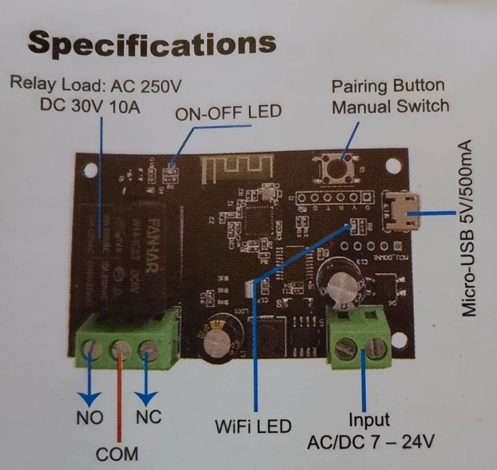
Recently I’ve bought few cheap DIY single relay boards. I need to control some electric water valves with that. As I hate cloud devices I’ve managed to swap original firmware with Tasmota.
The board comes with an ESP8285 onboard that can be flashed with Tasmota, but not out of the box as it is. After a bit of looking around and probing I found that this is because there are two 100ohm resistors that connect from the Rx and Tx pins of the ESP to the Tuya MCU.
This connection prevents the flashing process to be performed correctly because at power on the TuyaMCU starts sending data to ESP.
To flash the board I had to desolder temporarily the two SMD resistors, R12 and R13, and then with Tasmotizer I uploaded the standard tasmota.bin.
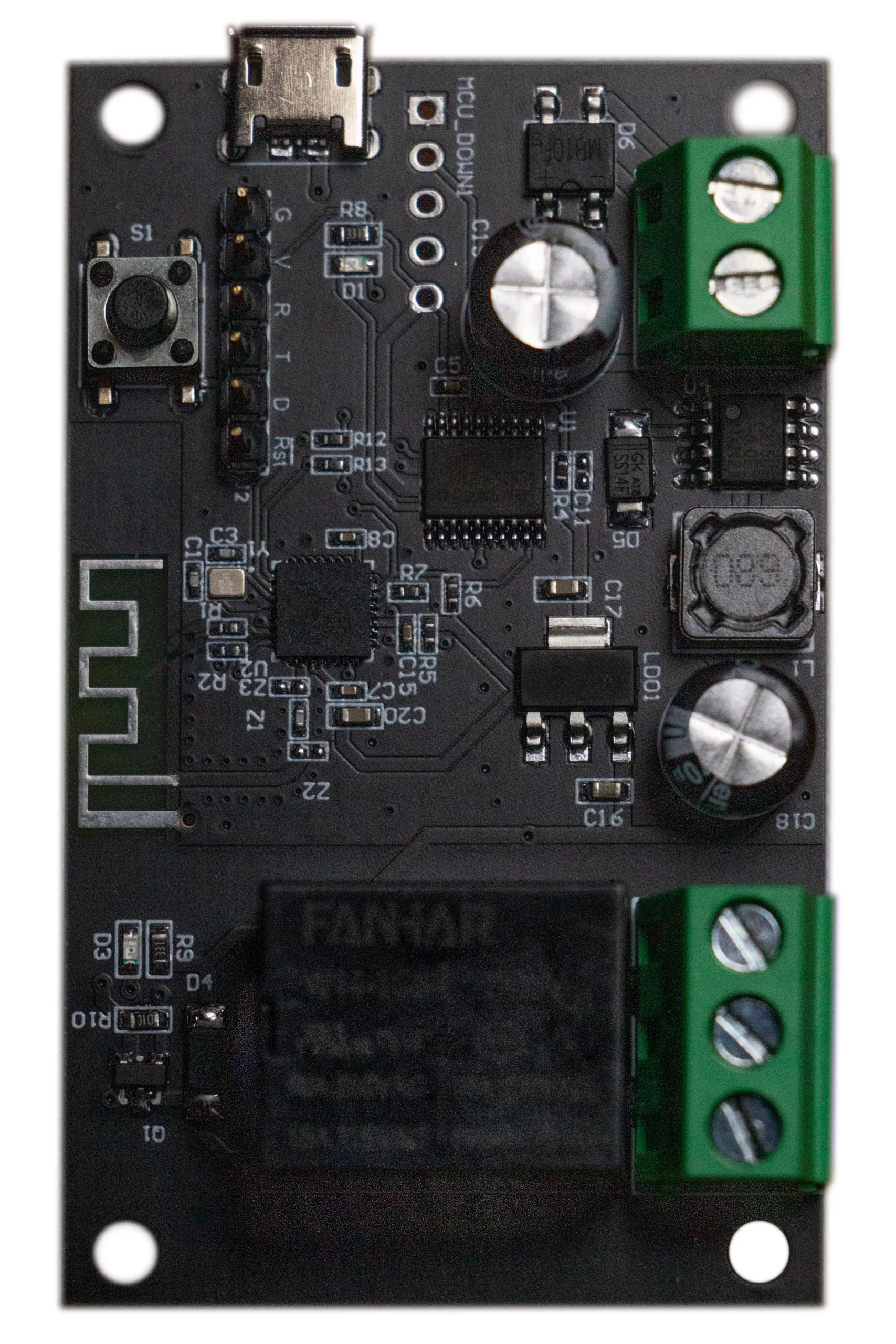
The pinout for the serial connection is correctly indicated on the board
G -> Ground
V -> 3.3 Volts
R -> Rx
T -> Tx
The switch S1 is connected to the GPIO pin that needs to be pressed at boot to enter in flash mode.
After a quick check on the tasmota web interface I soldered back again the resistors and configured the custom parameters as follows:
{"NAME":"Tuya TY-DIY-S01","GPIO":[1,1,1,1,1,1,0,0,1,1,1,1,1,0],"FLAG":0,"BASE":54,"CMND":"TuyaMCU 11,1 | TuyaMCU 1,101"}If you loose desoldered resistors – don’t mind that. It’s OK to use thin wire as the resistors – board will work normal without the resistors. Wire connection is enough.
Dodaj komentarz